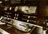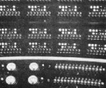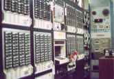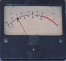

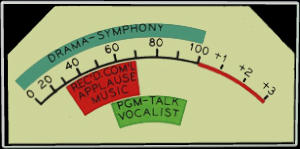
VU Meter from RCA Console
Some were still used for The Great 98
The Studios
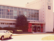
Riggs Bank Building
WRC started out in the Riggs Bank building at 14th. And Park Road.
The entire operation was self contained there with offices, studio, transmitter, and an antenna on the roof.
National Press Building
Next the studios moved to the Press Building at 14th. and F.
Interestingly, later in the 1970s the radio network briefly moved back into the Press Building.
The Trans-Lux Building
The next location in the 40s was the Trans-Lux building on 14th. Street between New York Ave. and H Street.
This building had the distinction of being one of the few buildings to be air conditioned in the 1940s.
There was a movie theatre in the building and news announcers would go into a booth to read headlines
to loudspeakers in the theatre.
There were 6 studios.
-Studio A was 39.5 X 25 and very live.
-Studio B was smaller and relatively dead.
-Studio E was similar to B
-Studio O was an announce booth
-Studio N was just like O but used by WMAL
-Studio C was just like B but used by WMAL
At this time the control room engineer only did mixing. The announcer did the channel switching
that was preset by the Master Control Room. The announcer had a panel called an Announcers Delight
that had groups of controls.
On the left were on and off buttons and tally lamps for Studio (the engineers mix)
Announce, Nemo, Transcriptions & Chimes. On the right were a carrier tally, setup and release keys
for local and network, and a carrier release key.
In the middle was a large button used to sound a beep when there was a news alert and an automatic
fader arm switch. When the automatic fader was armed, the cut on and off buttons would fade
rather than cut.
The delight was also used to switch to remote locations within a show. A particularly awkward situation was
the Morgan Beatty news at 7:30PM during which the commercials came from Chicago.
The radio network at this time was a "Round Robin" or loop. It would become unstable and feedback
unless there was one opening in it. The announcer in the destination city had to open the loop quickly
on the cue. The announcer in the releasing city had to pause a beat before repeating the network.
This situation was nicely automated later by heavy logic and then returned in the 1970s.
The transmitter site at this time was established on Ager Road in Prince Georges County Maryland.
The building contained an RCA 5-D transmitter and had enough space to install a second which was
to be for WMAL. That never happened and eventually 5-H and 5-U transmitters were purchased.
The final transmitters used were Collins Power Rocks.
The Wardman Park Hotel
The Trans Lux studios were fine for radio, but there was no room for television.
On May 25, 1947 TV operations moved to the Wardman Park (later the Sheraton-Park) hotel on Calvert St.
Later in October of 1952 on very short notice radio joined TV at the hotel. Most of the radio broadcasts
were done out of one studio. The radio recording room also had a studio associated with it but
no real board. Instead OP 6 & 7 field mixers were used.
The Washington Color Plant - 4001 Nebraska Ave.
In 1958, everything moved to 4001 Nebraska Ave.
Originally there were 3 TV studios, 4 radio studios, and 2 announce booths.
There were 3 identical radio control rooms and one small two fader intercept control at transmission.
It is important to understand that this was pre-transistor time. All amplification was vacuum tube.
All logic was realized with relays. The relays ran on 24 volt positive ground power called Plant Battery.
There was no such thing as a self contained audio board or video switcher.
The engineers used control surfaces, the amplifiers and relays were in racks.
Objectionable commercial loudness was a big deal at this time. NBC not only published a flurry
of memos on the subject, but actually took the unusual step of making a custom scale for the
volume indicators. These meters were used in all radio and TV control rooms. In New York they went
to the extreme of making up smaller scales for the meters on the RT-21s.
Radio Studios
Studio 1, the largest of the studios, was located in the center of the radio island in the basement.
It had the capability of 6 microphones. Studio 4 was located immediately behind it. Studio 4 had 4
microphone capability and was intended primarily as a rehearsal studio. It was rarely used for that
and was soon converted into Betty Groeblis office.
Studios 2 and 3 were on opposite sides of Studio 1. Studios 2 and 3 were two microphone announce
studios. Studio 2 was usually used for network news and studio 3 was used for local.
There were two small triangular announce booths, one for radio and one for TV, located adjacent to TV
studio C.
The radio booth was soon abandoned in favor of a news booth located in the first floor newsroom.
Eventually a second news booth was added on the first floor to segregate the network and local news
operations.
There was a sound effects truck in studio 1 that had two RCA 70D turntables and an OP6.
All studios had "Delight" boxes for the announcers. The boxes had a fader to control loudspeaker level,
assignment buttons to select which control room to work with, a bank of 11 headset select buttons
to listen to incoming feeds or the AM air, three intercom buttons to talk to the control rooms,
and a microphone switch. No more channel controls! The loudspeakers monitored the assigned
control room program when the microphones were off.
If a microphone was active in a studio, the loudspeaker got the MFB (Music Feed Back what we now
call foldback) feed from the control room. It was possible to have a microphone open in more than one
control room. In that case, the highest numbered control room MFB would win out.
The engineer had 3 MFB select keys which enabled mixing turntables & tape, nemos, and a spare jack
input. The SA (studio address) would interrupt the loudspeaker if the microphones were off or
if the studio was in rehearsal. When the microphones were on in program, the SA was inhibited through
the loudspeaker. The microphone switch controlled only the A microphone in each studio
(unless specifically changed by patching). It was a three position switch. Up was off locking, the middle
was on, and down was momentarily off for cough. All of this was heavily interlocked with relay logic so
the MFB, SA lockout, Signs, etc. followed the switch. The headset select was rarely used.
Most announcers did not wear headsets.
Control Rooms
The control rooms consoles were custom designed and built by NBC using RCA vacuum tube amplifiers
mounted in racks that formed the walls around control room 1. Three types were used.
Microphone and booster amps were model BA-21. This was a 40 dB gain microphone preamp.
Program and monitor amps were model BA-24. This was a mic. level in 10 watt amp originally designed
for monitoring. They were also used for program amps. We also had some BA-25 AGC amps that were
used for intercom. No BA-23 program amps were used in radio. TV had a few in the control rooms for
utility amps. The bus level was 22 that’s 30 dB below +8. This was before distribution amps.
We got a lot of feeds by taking a BA-24 and terminating it with a power resistor and then doing
30 dB bridging pads.
In 1968 when I started the entire plant was vacuum tube electronics. The only transistors were in the
RCA RT-7 cart machines.
All control room monitoring was RCA LC-1 in the triangular wall cabinets. The studios had the RCA SL-8s.
The control rooms had the capability of controlling microphones out of any studio. There were
10 microphone faders on each board. Two were dedicated to studio 2. Two were dedicated to studio 3.
The remaining 6 were switchable. All could be selected to studio 1 or the first four could be individually
changed to studio 4. The last 2 were either studio 1 or a booth. The final configuration had studio 4
replaced by the local news booth.
Each control room had four turntable/tape faders. Each of these faders had two keys and two lamps
associated with it. One key was for a turntable, the other was for a tape assignment from a tape room.
Originally there was only one tape room called Radio Recording located in back of control room 3.
It could assign 4 machines to any of the control rooms. Eventually 3 more rooms were constructed with
varying degrees of assignment. Control room 1 had 3 turntables. Control room 3 had 2 turntables and
control room 2 had only one that was never used. All turntables were RCA 70D. Later some were replaced
with Fairchild belt drive turntables.
RCA RT 7 & later 27 cart machines were used.
Each control room had one NEMO fader coupled to 10 job keys for remotes. Later control room 2 had
a small submixer built to handle 10 additional remotes. Job 10 was used for the radio network and was
heavily interlocked. More about this later.
There were also two additional faders on each board labeled "spare" and "echo" that appeared on jacks.
They were patched up to create a submix for the Joy Boys so the announcers cough switch could control
both the A and B microphones.
Radio Recording had 4 Ampex 350 machines which we really liked. There were also two RCA RT-4
machines which were only used for overflow recording and editing.
There was a RT 27 cart recorder later replaced with an ITC-RP. We also had two Scully lathes.
By the late 60s the lathes were only used to record material for the TV control rooms that did not have
cart, machines. Later the RT-4s were replaced with RT-21s. A second small room called radio production
was built about 1970 that had 2 RT-21s, an RT-27, & a turntable,,,it was an EMT packaged
in an RCA blue cabinet.
Channels
There were 6 channels to feed out of the plant. The switching was done by the control room operators
with the capability of transmission to interrupt. This was a radical departure from previous plants where
the announcer in conjunction with a master control room did the channel switching.
Channel 1 fed the circuit to the AM transmitter. Channel 2 fed the radio network. Channel 3 was a spare.
Channel 4 fed the FM transmitter. Channel 5 was a spare for 1 and 4. Channel 6 was a direct circuit to
New York called the "WAN". The switching was a preset, release operation.
When a control room was finished with a channel, it would release it, the channel would then go to a
control room that had preset the channel. If no control room had preset the channel, it would become
available and green talleys would light in every room.
Transmission had the ability to interrupt channels 1 and 4 and put the radio network on them.
This was done by taking the carrier away from the control rooms. Each control room had a red, illuminated
carrier button associated with channels 1 and 4. The carrier button went out when transmission took control.
A control room with a channel up could take control back by pressing the button. The AM channel one
carrier button was modified to flash in the control room with the channel when carrier was in transmission.
The channels were interlocked with the SA so that when a microphone was open with no channel up a
rehearsal sign lit and SA was not inhibited, but the control room loudspeaker would mute.
When a channel was up, SA was inhibited and the on the air sign was lit.
The channel relays were also interlocked with AT&T and the other O&Os. The eastern radio network had
several reversible circuits called the RAC connecting the O&Os with the affiliates split off of those lines.
An additional reversible circuit, the PC connected San Francisco with Chicago. Any O&O could feed the
network by picking up the network channel. When the feeding station released the channel,
the network would switch to the next preset location.
Just like the studio channel switching only one level higher. In our case, that was controlled by Channel two
and job key 10 with 3 talleys, green for RAC receive, red for RAC transmit, and white for cue which really
meant switching in progress. This was later cut back to a round-robin connection in the northeast.
The logic then simply drove AT&T relays that either bypassed or inserted Washington into the loop.
TV had exactly the same round-robin switching interlocked with the Nemo 1 button and the TV channel
switching.
In the late 60s, FM went stereo with a Schaffer automation system which was called the automatic
programmer. This worked as an interrupt of channel 4 or 5. Logic was built up so that the stereo pilot was
only on when the programmer was on the air and not on its network source.
In 1969, a small stereo control room was built with an RCA BC19. The room had the ability to control the
pilot when it had channel 4 up.
The Great 98 Project
It was obvious the studio 3 and control room 3 were the places to rock and roll. We replaced the
mic preamp and microphone booster amp which had been RCA BA21s with Melcor cards. These were
brick op amps similar to those later made by Automated Processes. We also got a neat little microphone
compressor built by EMT.
The studio monitor was beefed up with an EMT OY. We installed a lamp with momentary buttons that
could be hit by either the jock or the engineer. This was supposed to be an atta-boy lamp that you hit
whenever you liked something. The jock also got a Tapecaster digital clock that used RCA Numatrons.
This was much better, but still pretty rough. We were still using well worn RCA RT-27 cart machines and
spinning records on the Fairchild turntables. The air chain was 4000 series Audimax and Volumax.
At this time, we always used Sennheiser 421s for announce.
William (Mike) Galvin and Geoffrey Bryan in the construction department started working on a new
outboard add on to control room 3. It as a lot better. It had 2 QRK turntables with Rek O Kut arms
and 2 ITC 3D machines. This was all controlled by a strip of API faders with start switches next to them.
They also provided a small box with a VU in it on a wire so you could see it as well as the original mixer VU
which was now in back and to the side of the engineer.
The ITC machines were an immediate problem as they had a different head arrangement than
the RCA RT-27 that we used to record the carts. We soon got and ITC RP recorder which helped a lot.
Air Chains
I’m not sure that I can remember this as we changed things so often...heres my best try:
-Originally there were only RCA BA-6s. There were regular and emergency limiters for all services.
The AM limiters were at the studios, not the transmitter site. The pre-emphasis networks were pulled out
of the FM & TV transmitters and installed before the limiters.
-A CBS labs Automatic Loudness Controller was purchased for TV as commercial loudness was a big
issue at that time. It was installed between the BA-6 and the transmitter.
-A CBS labs Volumax 400 was purchased for AM but was installed in the studios and was not considered
a success. It soon was only used in the emergency path.
-FM went stereo and got a complete RCA package of BA 45, 46, & 47 which sounded dreadful.
-AM got 4000 series Audimax and Volumax in about 1971. This was a huge improvement.
About this time we also got some Fairchild equalizers but did not use them successfully.
-AM got an EMT mic. Compressor which worked very well.
-The Fairchild equalizers were not successful, so we tried a McCurdy equalizer. We didnt like that either.
-FM went Shulke (Stereo Radio Productions) and we were told by Shulke that we must have a stereo 400
series FM Volumax. So that is what we bought. It worked ok.
-Next AM got an UREI LA-3 and a SpectraSonics Complimiter. The LA-3 was great,
no one liked the Complimiter.
-Near the end of the Great 98 we got an early model DAP (Discriminate Audio Processor). This was a 3
band compressor with an overall peak limiter designed by Michael Dorrough who makes the LED meters.
It seemed to be good, but unstable. We had to continually adjust the FET biases. After a few months,
Dorrough called up and said that there were power supply problems that were easily cured by removing
the meter lamps. We did and the thing became totally stable. We eventually settled on the DAP at the
studios with the output limiter bypassed and the Volumax 4000 at the transmitter site for AM.
This configuration was in place for the end of the Great 98 and most of the NIS period.
-Somewhere in here we got a Kahn Symetrapeak but only used it briefly.
-We next got a pair of the original Optimods for FM. Definitely a loudness improvement, but we didnt like
the way they sounded on speech. We experimented with putting a pair of LA-3s in front of them but still
were not really happy.
-Ted Ronneburger was hired as chief about this time. He previously worked in NY at 99XLO (WOR-FM).
All agreed that was a great sounding station so we duplicated the 99XLO processing for FM and the WOR
processing for AM. That was for AM a Pacific Recorders limiter and for FM DAPs with a Mosely peak limiter.
I believe that at time we were using an LA-3 as the mic compressor. Teddy was very wise....this was
certainly the best that both stations had ever sounded.
-I believe that processing was in place for AM until the stations moved to the new addition in the back
of the building. At that time AM went with Orban 424 units at the studios.
-FM, on the other hand had some bad days. The first step backward came with Double DAPs.
This is hard to believe, but we actually paralleled DAPs. It was supposed to be louder and maybe it was
but it sure sounded messy. Next the Mosley limiters went and the Optimods came back.
Worse, one of the Optimods had a defective release time module making it very fast. Unfortunately that
was the one that was preferred! UREI graphic equalizers were added. The station was sounding really
bad at this time and no one was happy and then the final insult to sensibilities was a composite clipper.
I dont remember the manufacturer. This thing might have been ok, but it was operated pretty drastically
and the pilot completely disappeared on kick drum beats. It had different effects on different radios but
definitely was terrible.
-FM eventually settled down to a newer model Optimod which sounded pretty good, but
what "a long, strange trip" it was to get there!

Dedicated to Mike Galvin
